cse • paper_2 • solid_state_electronics
[UPSC CSE 2026] Semiconductors/Solar cell (Q147, 20M)
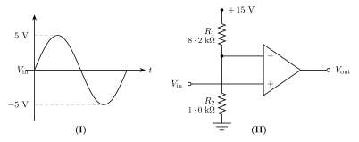
The input signal as shown in Figure (I) is applied to the comparator circuit given in Figure (II). Make a sketch of the output signal showing its proper relationship to the input signal. Assume that the maximum output levels of the op-amp are \pm 12\text{ V}.
Discussion (0)
Sign in to post a solution, derivation, or discussion.
No comments yet. Start the conversation!